Introduction | Tank – How to | Tank – Examples | Atmosphere – The Polar Front | Atmosphere – Synoptic Fronts | Theory | For Teachers | Wiki
Here we describe a laboratory experiment in which a cylinder of salty water collapses under gravity and rotation and sets up a swirling vortex with a distinct frontal slope. We measure the slope and the speed of the currents and interpret them in terms of the thermal wind relation.
How to carry out the cylinder collapse experiment
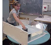
We take our clear 16”x16” square container and place it dead center on a white board on the turntable. and fill it with water to a depth of 10 cm or so. We then take a hollow metal cylinder, generously rub petroleum jelly around its lower rim and place it in the center of the tank so that it protrudes slightly above the surface – see picture to the right. (A suitable cylinder, roughly 10cm in diameter, can readily be made by taking the lid off both ends of a coffee bean can.) Sufficient saline solution is prepared to fill the hollow cylinder by dissolving as much salt as possible in to tap water at room temperature. Colored dye is then added.
The table is set in to rotation at a speed of about 15 rpm or so and allowed to settle down for 10 minutes or so to achieve solid body rotation. While the table is rotating we carefully and slowly remove the water within the cylinder and replace it with dyed, saturated salty (and hence dense) water delivered from a small beaker. When the hollow cylinder is full of colored saline water, it is rapidly removed in a manner which causes the least disturbance possible.
The column of dense salty water slumps under gravity but is `held up’ by rotation forming a cone whose sides have a distinct slope (see below schematic). The cone acquires a definite sense of rotation, swirling cyclonically at its top (in the same sense of rotation as the table). We measure:
- the density of the dyed water;
- typical surface speeds above the cone at specific points making use of paper dots;
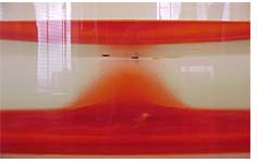
- the slope of the side of the cone (the frontal surface) by taking a picture that captures the front and surface paper dots when they are aligned in a plane that is parallel to the camera (see photo below). Three particles seem to do the trick – two placed at different locations over the cone and one placed in the far field as a reference.
The slope of the frontal surface and the speed of circulation can be interpreted in terms of the thermal wind equation and the Margules formula, as discussed here.