We describe here the basic equipment required to carry out the experiments:
: rotating turntable equipped with slip rings, video camera and display
: fluid tanks
: auxiliary equipment
: fluid cart equipped with storage tank and pump.
For more information on the equipment (turntable, cart, camera, video display, motors, electronics, pumps, tanks) required to carry out any of the experiments, contact John Marshall (jmarsh@mit.edu).
Note: All the equipment described here – the turntable, mobile cart, fluid tanks and auxiliary laboratory materials – is manufactured, and can be supplied by, Dana Sigall (dsigall@gmail.com ), a craftsman working in Gloucester, Massachusetts.
Rotating table
The central piece of equipment required to perform the experiments is a turntable. The turntable we have designed is shown in the photographs below. The turning platform — the dial — is 18 in. × 24 in and can be made to spin at rotation periods in the range 2 seconds to 60 seconds: i.e. at a rate of 30 rpm (revolutions per minute) down to 1 rpm, and is measured by a digital readout. The turntable has a simple but effective design; drive is achieved through a friction wheel on the underside of the dial driven by a variable speed motor. The experiments are typically carried out in a square 16 in. × 16 in. tank placed on the rotating dial.
You can look at more detailed views of the turntable by clicking on the images below.
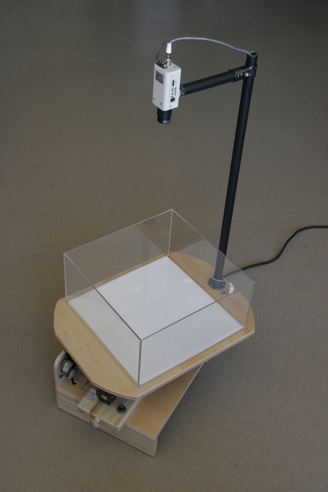
The experiment is viewed from a video camera co-rotating with the dial, whose signal is passed through a slip ring for display in the laboratory frame, either on a monitor or a projection device. Power to the table is only 12V, an added safety feature because of the close proximity of water, but sufficient to power (via the slip ring) pumps and fans in the rotating frame. The table itself is sturdy and lightweight, being constructed of high-quality, cabinet-grade plywood and finished with a water-resistant precatalyzed lacquer.
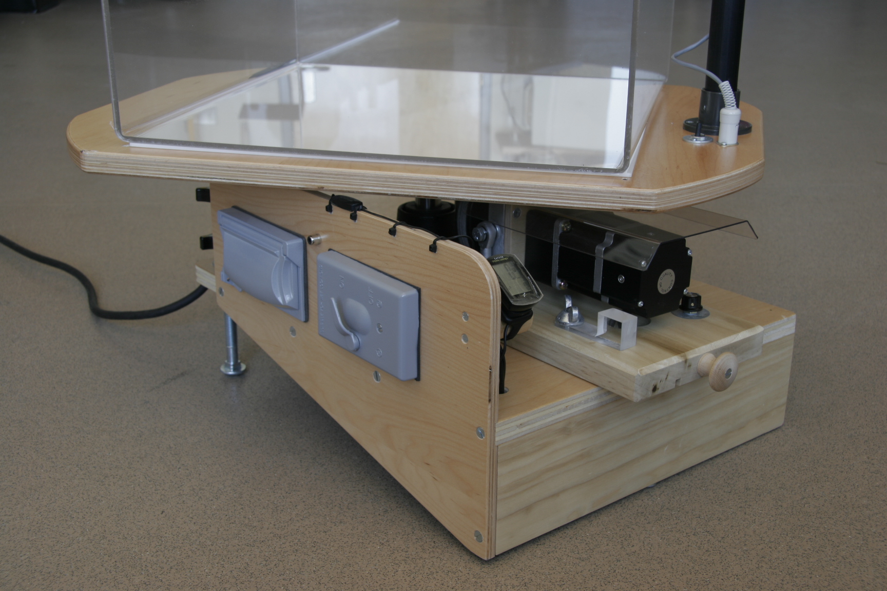
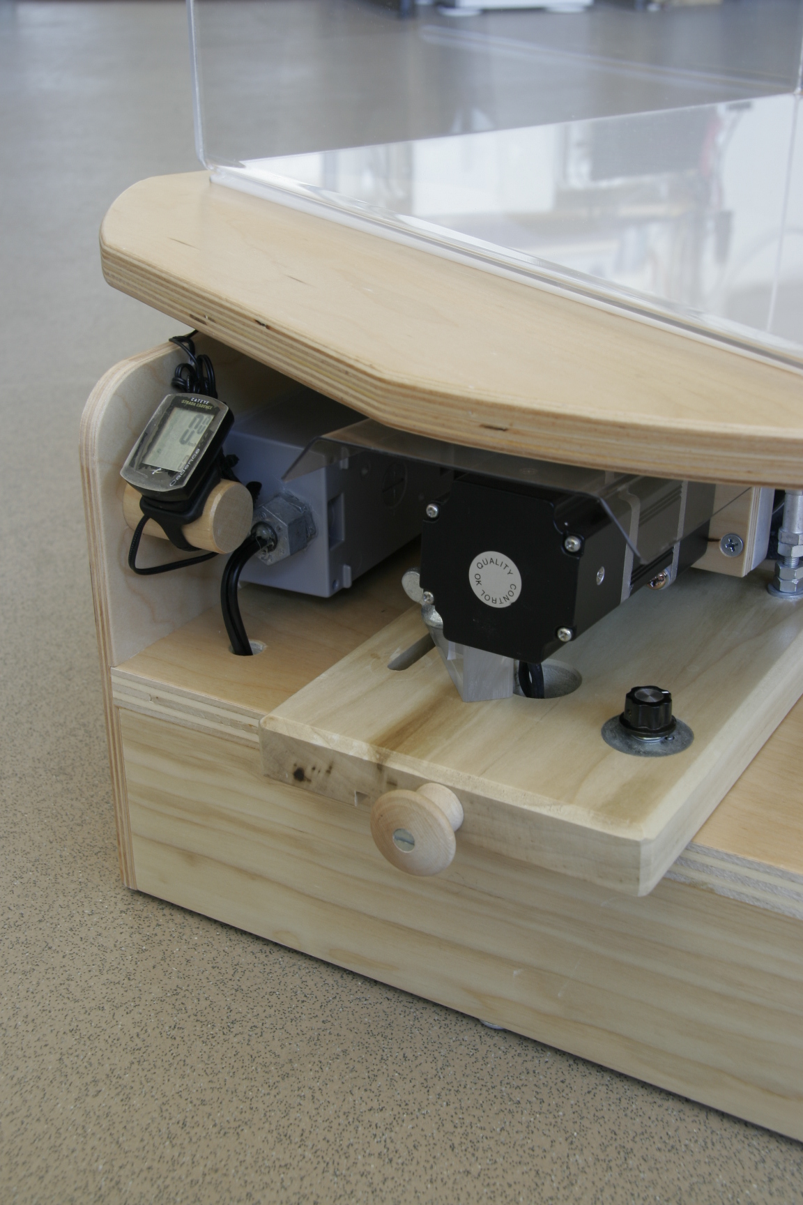
Drive Mechanism
The drive of the turntable is achieved by a friction wheel on the underside of the dial driven by a variable speed motor. You can view the drive mechanism here:
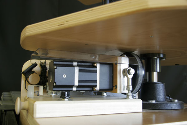
The novel friction drive mechanism has a number of advantages over a more conventional direct-drive via a timing belt: (i) it provides an automatic clutch allowing the dial to be readily stopped in a safe manner without damaging the apparatus or the user! Indeed one can grab hold of the turning dial bringing it abruptly to rest with no un-toward consequences (ii) its simple but effective design allows one to slide the friction wheel radially inwards (increasing the rotation rate, Ω) or outwards (decreasing Ω). Combined with the adjustable speed of the motor, a continuous and wide range of possible rotation rates can be achieved between 1 and 30rpm.
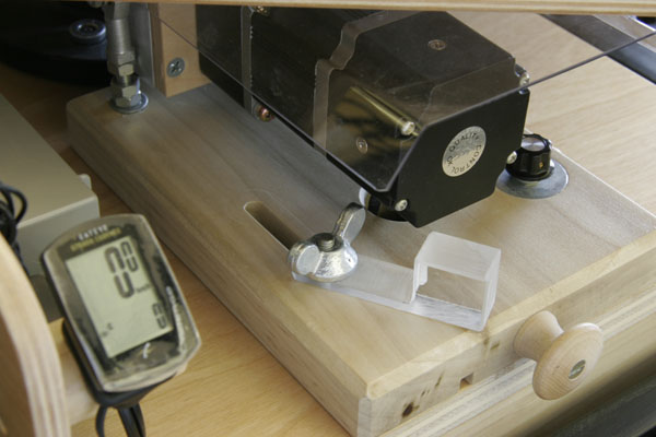
Tachometer
The tachometer makes use of the cadence function of a cyclometer (see below) and does not need to be calibrated. The rotation rate reads in the lower right corner of the cyclometer. Click the cyclometer face to enter the cadence readout mode indicated by a small “C”. In order to align the device’s sensor to an appropriate dial rotation range, ten sensor magnets are set in the underside of the dial. Add a decimal place to the readout for the actual dial rotation rate, e.g., 102 =10.2 rpm (revolutions per minute).
Note: you will find that the turntable may be capable of rotation rates both slower and faster than registered by the cyclometer but most useful rotation speeds are covered. In particular, stable rotation rates of less that 1rpm (which are achievable with the turntable and useful in, for example, Hadley Regimes) are beyond the range of the cyclometer. In this case directly measure the rotation rate with a stopwatch.
Video Camera and slip-rings
Experiments placed on the dial can be viewed in the rotating frame from a video camera (through a zoom lens) mounted on an arm that rotates with the dial. The video signal is passed from the rotating frame through a slip-ring. A video cable can be conveniently plugged in to a socket on the turntable base and the camera view displayed in the non-rotating frame on a TV/computer monitor, beamed up on to a large screen for viewing by many, or captured by a computer.
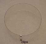
Fluid tanks, white base and circular insert
Experiments are carried out in clear acrylic tanks placed on a white plastic base centered on the dial. A 16″x16″x8″ tank is found to be convenient. A circular insert readily converts the square tank in to a cylindrical one. The circular insert, secured by stainless steel clips, is shown in place below. A stainless-steel container placed in the middle is weighted down so that is does not float when the tank is filled with water. When ice is added to the container, a radial temperature gradient is created.
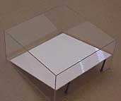
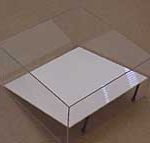
In most experiments the water tank is placed on the white plastic base centered on the dial (this makes the view through the camera uniform and bright). However, in some experiments a tilted base is required. In this case the white plastic base serves as a ‘false bottom’: it is inserted insidethe square tank and tilted to mimic spherical effects. The base is conveniently tilted through the use of spacers (a plastic bolt or upturned hockey puck).
Auxiliary materials and equipment
Useful (indeed, rather essential) auxiliary equipment is shown in the photographs below and comprises:
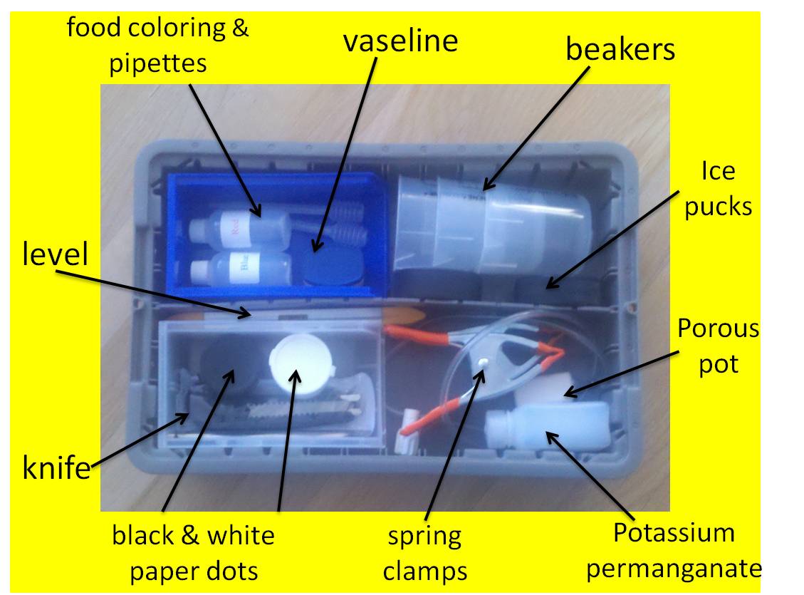
In the square plastic container (click on the image below):
– plastic bottles for dye (food coloring) and to hold potassium permanganate
– spatula (for potassium permanganate)
– pipettes (for food coloring)
– black (white) plastic containers for black (white) paper dots
– Vaseline (for the Fronts experiment)
– ice pucks (for the Taylor Column experiment and, when upended, to tilt the false base)
– sharp knife
– three orange spring clamps (various uses)
– porous pot with associated tubing including flow rate regulator (various uses)
– three plastic beakers (for balanced vortex experiment and general use)
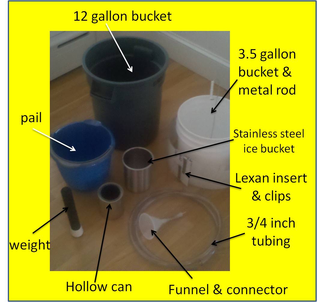
In addition, further useful auxiliary equipment is (click on the image below):
– 10 gallon grey bucket and 10 quart blue spout pail (general use)
– white 3 1/2 gallon bucket with stoppered hole in center (for balanced vortex experiment)
– a metal rod to remove the stopper from the white bucket (for balanced vortex experiment)
– a hollow silver paint can (for the front experiment)
– stainless steel ice bucket (for the general circulation experiment)
– a black metal weight with flat rubber base (to weigh down the ice bucket)
– Lexan insert with stainless steel clips to place inside the square acrylic tank, rendering it circular
– immersible bilge pump for filling and emptying the acrylic tank powered by a 9VDC transformer
– (alternatively) a thick (3/4″ inside diameter), 6′ long tube for siphoning water from the acrylic tank.
Fluid cart
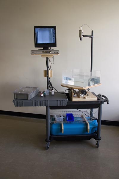
The turntable can be installed on the mobile cart (click on image below) which can be used to transport the equipment to where it is to be used and as a platform to carry the experiment. The cart is equipped with a 10-gal water storage tank (blue) and pump, a tray to store and carry assorted materials—such as ice buckets, cans, beakers, dyes, among others—and a post on which to place a liquid crystal display (LCD) television monitor for convenient display of the experiment from the rotating camera.
Three 110 ac ground fault circuit interrupter (GFCT) power outlets are supplied on the monitor support of the fluid cart to power the 12V system, video monitor, and any other ancillary equipment.
LCD television Monitor
The output from the turntable video camera can be fed in to a LCD television monitor which is installed on the cart or any other useful devise such as a DVD recorder and/or projection device or computer for use with large audiences.
For further detail on routing video for demonstrations and analyses, see:
Recording video from turntable