Introduction | Tank – How to | Tank – Examples | Wiki
We take our clear square 16” x 16” tank and position it on the center of the turntable. We then place our tall narrow rectangular tank inside the large square tank and push it flush against the side. To represent the effect of the earth’s sphericity on Taylor Columns, we create a sloping bottom by dropping in a rectangular plastic sheet cut to fit inside the large tank whilst abutting up to the tall tank at an angle. The whole arrangement can be seen in Fig.1 (left).
[Note that in this experiment the tall tank is only being used as a convenient support for the sloping bottom, enabling us to reuse equipment designed for the thermohaline circulation experiment. The tall tank can be dispensed with.]
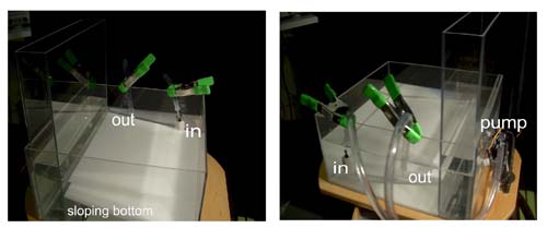
Fig.1 Arrangement of the nozzle (labeled out) and diffuser (labeled in) and the pump. Spherical effects are represented by the sloping bottom.
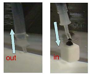
Fig.2 Left: the nozzle through which the water is drawn out to the pump. Right: the diffuser through which water flows in to the tank.
The initial set-up of the pump and associated tubing is carried out without filling the tank with water. A pump with 1⁄2 diameter tubing is placed on the turntable adjacent to the camera mount, as shown in Fig.1 (right). A 12V water pump used for cooling PC’s is ideal. Water will be drawn from the tank in to the pump through a nozzle (as shown in Fig.2, left) and pushed out of the pump in to the tank through a diffuser (as shown in Fig.2, right). The arrangement of the pump, together with the tubes running to and from it, can be seen in Fig.1. The tubing is affixed to the side of the tank using the green clamps shown in the figure. Be sure to arrange the clamps so that the nozzle and diffuser and associated pipes enter the water at right-angles.
We now (i) pour water into the tower to a depth of 10cm or so (ii) fill the large square tank until water completely covers the slanted bottom to a depth (at the shallowest point) of about 2 inches.
The water pump is now charged by detaching the diffuser (Fig.2 right) and drawing water – e.g. by sucking! – through the pump until there is enough water in the pump for it to operate. Rather than sucking, the pump can be charged somewhat more elegantly by pouring water down the 1⁄2” pipe in to the pump using a funnel. Once charged the pump is turned on. If all is working correctly, water will be drawn out of the tank, through the pump and in to the tank again. Once the pump is functioning the diffuser is reattached and submerged as in Fig.2 (right).
The flow rate must be reduced to a trickle – about 100ml per minute, or less. If necessary, this can be achieved by using the clamps to constrict the flow in the 1/2 “pipe.
Once set up with water being drawn through the pump slowly, in to and out of the tank, the turntable is spun up to a speed of 10rpm or so and left for 15 to 20 minutes until a steady state is achieved.
The flow is best visualized, as in Fig.3 , by injecting a slug of dye adjacent to the inflow diffuser. One dye injection should be sufficient.
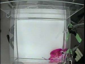
Fig. 3. Dye is used to visualize the flow by injection adjacent to the inflow diffuser.
Several arrangements can be tried, as shown in the diagram below.