Introduction | Tank – How to | Tank – Examples | Wiki
The photographs below chart the flow patterns that connect a source (flow in to the tank) at the bottom rhs to the sink (flow out of the tank) at the top rhs. The poleward (shallow) side of the tank is at the top. Over a period of several minutes, red dye injected adjacent to the source (top left panel) tracks westward (bottom left), turns poleward along the western boundary before turning eastwards at, roughly, the latitude of the sink (top right). The dyed fluid is ultimately drawn out through the nozzle (bottom right).
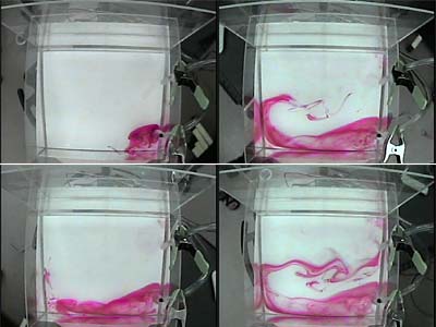
In this experiment considerable (and perhaps excessive) local circulation was developed in the vicinity of the sink directly associated with the extraction of fluid through the nozzle. It may be beneficial to employ a diffuser at the sink as well as the source. Reduction of flow rates also leads to a weaker circulation.