Introduction | Tank – How to |Tank – Examples | Atmospheric – Examples | Theory
The experiments described here investigate Rossby waves generated by flow over a barrier on a beta plane.
How to Carry Out the Experiment
Take the clear 16”x16” square tank and position it centrally on the turntable. Place the cylindrical insert inside the square tank. Next, place a cone into the tank that fits snugly against the cylindrical insert, and then fill the tank with water so that the water level is slightly below the top of the cone (see Fig. 1). Place a small barrier along one side of the cone. A barrier made of an aluminum bar of dimension 1/4” thick by 1” wide by 8 ” long works well.
The cone used was constructed from a thin circular plastic sheet with the point of the cone removed to make the plastic easier to work with. A slope on the cone of around 1 seemed to work well. The varying depth of the tank mimics the variation in the depth of a spherical shell of fluid measured in the direction parallel to the rotation vector on the sphere (see the theory section). The shallow end of the tank is analogous to the poleward flank of the fluid and the deep end to the tropics, so the center of the cone represents the pole, and the outer edge of the cone represents the equator.
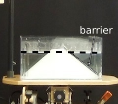
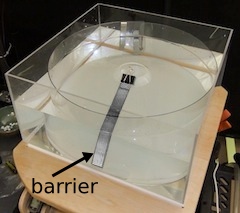
Fig.1. Arrangement of apparatus for the flow over a barrier on a beta plane experiment. A conical bottom is used to mimic spherical effects, the shallow zone representing the pole. The dotted line marks the water level. A circular insert renders the square experimental tank circular.
Set the table rotating at a speed of around 15 rpm or so. The experiment consists of decreasing the rotation speed of the turntable by approximately 1 rpm once the water is in solid body rotation. It is useful to get a feel for how much of an adjustment to the motor this involves before starting the experiment. Wait for 15-20 minutes until solid body rotation is attained by the water – this can be tested by seeing if paper dots dropped onto the surface of the water remain stationary with respect to the rotating frame (i.e., viewed through the corotating camera).
Once the system is in solid body rotation, streak the water with circular bands of dye either by dragging the pipette through the water as dye is released, or by releasing several points of dye. It is important to not use too much dye, particularly when placing it close to the centre of the cone, since excessive dye will run down the sloped bottom. The most important area to place a band of dye is roughly two-thirds of the way from the ‘pole’-water boundary to the edge of the tank, since this is where Rossby waves are most clearly seen.
Once the dye has settled down, the experiment can begin. Carefully reduce the rotation speed by approximately ΔΩ = 1 rpm. Immediately after this, the tank will be travelling with angular velocity Ω – ΔΩ, whilst the water continues to travel with angular velocity Ω, leading to anticlockwise (or “eastwards”) flow of the water (see Fig.2), with relative angular velocity ΔΩ.
It can also be informative to place paper dots on the surface of the water and track their motion using a particle tracker.
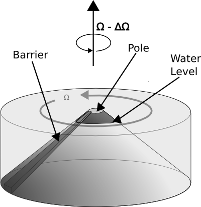
Fig.2. Schematic of experiment immediately following change in angular velocity of tank.
As water travels over the barrier, Taylor columns attempt to maintain their length, and so the flow is forced towards the outside of the tank (i.e., equatorwards, to the deeper parts of the tank), resulting in the generation of a Rossby wave.
We are most interested in Rossby waves whose phase speed exactly cancels the relative speed of the water compared to the tank, i.e., Rossby waves which are stationary in the tank.