We are all familiar with the swirl and gurgling sound of water flowing down a drain. Here we explore a laboratory illustration of this phenomenon and study it in rotating and non-rotating conditions. The experiment involves setting up a fluid vortex, measuring the associated flow and interpreting measurements in terms of associated theory.
We rotate a cylinder filled with water about its vertical axis: the cylinder has a circular drain hole in the center of its bottom. The water flows inwards conserving angular momentum and, in so doing, acquires a swirling motion, as sketched in the figure. The swirling motion can become very vigorous if the cylinder is rotated even at moderate speeds, because the angular momentum of the cylinder is ‘concentrated’ by inward flowing rings of fluid.
Flow patterns (left) in the absence of rotation and (right) when the apparatus is rotating in an anticlockwise direction.
We take a cylindrical plastic bucket about 30 cm in diameter and 50 cm high with a one centimeter hole in the center. Plug the hole with a stopper and position the bucket evenly on top of three upside-down 100mL beakers in the square plastic container on the rotating table, as indicated in Fig.1. Reposition the bucket as necessary so that it is dead center in the square tank which is itself centered on the rotating table. The plug in the center of the bucket should then be coincident with the axis of rotation.
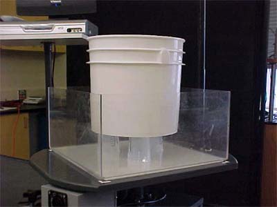
Fig.1: Plastic bucket positioned at the center of square tank on the turntable
Be careful not to plug the hole too tightly: it should be just snug enough to support the weight of the water, but easy to release. Verify that the interior of the bucket is level and add water until about 7/10 full and mix in one or two drops of dye to aid in visualization, as shown in Fig. 2.
Set the turn-table to a rotation rate in the range 10-15 rpm and wait for 10 minutes or so until the system is in solid body rotation (check by floating a paper dot onthe surface it should be stationary in the rotating frame, i.e. as viewed from the camera co-rotating camera above).
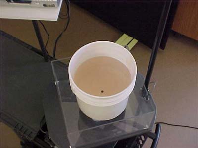
Fig. 2: Bucket filled to an appropriate level with tinted water to aid visualization
While waiting for solid body rotation to be attained, use the particle tracker software to determine and record both the coordinates of the center of the bucket and the radius of the circle defined by the water level. Also, using the tracker software, be sure to mask out the center hole and the region peripheral to the bucket; your screen can be centered on the bucket by double clicking on the center hole.
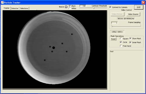
Fig. 3: The experiment as it appears in the particle tracker viewer at the start of the experiment. We see 6 black paper dots floating on the surface. The stopper at the center of the tank is also visible.
When the system is in solid body rotation, add several black paper dots at different radii from the center. Then, with good timing, poke out the plug with the metal handle. This can be a bit tricky – take care not to hit the camera or disturb the system more than necessary. We found it useful to grasp the handle with both hands, one lower down on the rod for guidance, the other higher up to provide force. Enter and exit the surface of the water as vertically as possible in order to avoid creating undue disturbance. Once completely out of the camera’s field of view, activate the particle tracker on the screen to determine the trajectory of each paper dot. Single particles can be tracked or multiple (up to 10) particles simultaneously.
We observe that the particles swirl around many, many times before exiting from the hole at the center. Particles on the outside move much more slowly than particles on the inside: as the particles approach the hole, they acquire a very strong swirling motion see Fig.4
The experiment can be carried out over a range of rotation rates.
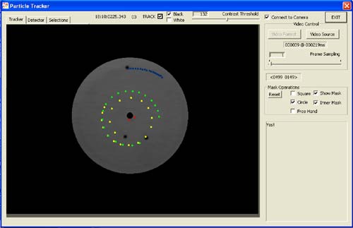
Fig. 4: Screenshot of the particle tracker viewer showing the trajectory of several particles every (roughly) 1/10th of a second.